Status Asthmaticus: The Art of Ventilating
- In ICU
- Thu, 24 Jul 2025
ICU Management & Practice, Volume 25 - Issue 3, 2025
Recognising the mechanisms of air trapping that cause status asthmaticus can help optimise the setting of invasive mechanical ventilation. This article provides an academic visual summary to facilitate understanding.
Introduction
Status asthmaticus can be life-threatening. Invasive mechanical ventilation is one of the therapeutic actions for its management, along with well-described pharmacological therapies. We present an updated summary to facilitate understanding of the mechanisms by which air trapping occurs.
Biophysical Concepts
Flow
From rheology, the Hagen-Poiseuille Law describes the incompressible and laminar flow of a viscous fluid through a cylindrical tube, considering important factors such as the length (meters) and radius (meters) of the tube, the dynamic viscosity of the fluid (Pa.s), the volumetric flow rate (L/min) and the pressure difference (DP) between both ends of the tube (mmHg). Some relevant considerations:
- Small changes in radius will dramatically affect the flow rate.
- More viscous fluids present greater resistance to movement.
- The longer the pipe length, the greater the resistance to flow.
However, if the flow velocity is very high, the laminar regime becomes turbulent, and the equation becomes invalid. If we take all of the above to the respiratory system, the equation (Ostadfar 2016) would be:
Q=( π R^4 ΔP)/8 η L
where
Q= air flow (L/s or L/min)
R= airway radius (m)
ΔP = pressure difference between mouth and alveoli (cmH2O)
η = dynamic air viscosity (Pa.s)
L= airway length (m)
Conductance is directly proportional to the pressure gradient and airway radius and inversely proportional to airway length and gas viscosity. Thus, the higher the driving pressure (DP), the greater the airflow.
The Reynolds number (Re) is a dimensionless construct that describes the relationship between the inertial and viscous forces in a fluid. It is calculated:
Re= ρVL/μ
where
ρ= gas density
V= gas flow rate
L= airway length
μ= gas flow viscosity
A Re > 2000 indicates that the airflow shifts from a laminar to a turbulent regime due to the development of disordered currents that increase resistance, leading to a decrease in conductance and ultimately to an increase in the work of breathing (Hudson et al. 2023).
Resistance
The inverse relationship of the flow equation corresponds to the description of airway resistance (Topalovic et al. 2015). Initially described as:
Raw=ΔP/Flow
However, more complex and complete descriptions, such as the viscoelastic models (Kelvin-Voigt or Zener) (Milic-Emili and D’Angelo 1992), include the elastic, viscous and resistive components in the equation. The frictional resistance to airflow through the airway can be calculated by means of:
σ=E* ε + η * (d ε)/(d t)
where
σ = stress, or mechanical stress on the bronchial wall
E= lung elasticity (related to compliance)
η = tissue viscose resistance
ε= strain, o relative airway deformation due to flow and pressure
(d ε)/(d t) = rate of change of deformation (strain rate)
Airway resistance is not constant and instead varies dynamically with lung volume. That is, at low lung volumes, resistance increases as the bronchi collapse, mainly due to a decrease in transpulmonary pressure. Likewise, at high lung volumes, bronchial wall tension may induce non-linear effects on tissue elasticity (Carvalho and Zin 2011).
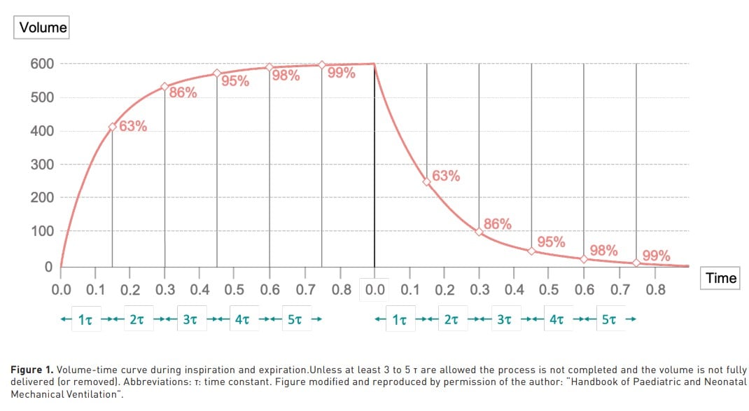
Time Constant
Represented by the Greek letter τ (tau), describes how quickly or slowly a given system responds to a change. Mathematically, it is defined as the time required for a system to reach approximately 63% of its total response to a change. The Maxwell model describes the viscoelastic behaviour of a material when subjected to a deforming force. In rheology, it represents the relationship between elasticity and viscosity in systems that respond with relaxation as a function of time (Elbirli and Shaw 1978). The time constant in the respiratory system describes the rate (in seconds) at which the lungs respond as a function of pressure changes. It is defined as the product of airway resistance and airflow resistance (Raw) and lung compliance (CL) (Depta et al. 2024). Therefore, 1 time constant (TC) represents 63% of the inspiratory or expiratory process (Shevade 2022). To complete 95% of the process, 3 to 5 TC are required (Figure 1).
Air Trapping: Mechanisms
From a rheological perspective, air trapping results from an increase in the viscosity of the ventilatory system. That is, high resistance produces high TC. Therefore, any increase in resistance (and/or lung elastance) in the airway will generate turbulent flow, which results in a slowing of lung filling or emptying, favouring volume trapping at the alveolar level. The usual way to determine dynamic hyperinflation is by an expiratory pause to visualise auto PEEP (aPEEP) or intrinsic PEEP.
There are three types of air trapping: dynamic (e.g. asthma), lower airway collapse (e.g. bronchiolitis, COPD) and valve mechanism due to secretions (bronchiolitis) (Medina and Modesto i Alapont 2021). For academic purposes, the following classification is proposed, based on the pathophysiological substrate of entrapment (Figure 2):
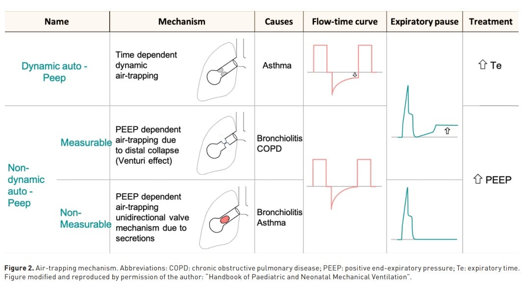
1. Dynamic air trapping: dynamic aPEEP
It is mainly due to time-dependent dynamic trapping. That is, there are < 3-5 expiratory TC, so that the next inspiration starts before the end of the previous expiratory cycle, and therefore there is no complete alveolar emptying. The flow-time curve shows that the expiratory flow does not reach the baseline. The pressure-time curve shows an increase in inspiratory resistance (Peak inspiratory pressure, Ppeak - Plateau pressure, Pplat). In addition, when an expiratory pause (PEEP of 0 cmH2O) is performed, an increase in pressure above the set PEEP is observed, which translates into measurable aPEEP.
The correct way to solve this type of trapping is to increase expiratory time (> 3 TC), allowing expiratory flow to reach the baseline and ensuring alveolar emptying. PEEP (after the expiratory pause at PEEP of 0 cmH2O) should not be set beyond 5 to 7 cmH2O
2. Non-dynamic measurable air trapping: non-dynamic measurable aPEEP
This is mainly explained by the collapse of the distal airway. In this case, in the flowtime curve the expiratory flow reaches the baseline and is therefore not detectable in this curve display because total obstruction during expiration generates zero flow. However, during the expiratory pause, the occluded distal airway becomes patent as the Venturi effect ceases (Neill and Hashemi, 2018), which actively collapses the distal airway during expiration. The detected trapped pressure during the expiratory pause in the pressure-time curve is then called non-dynamic measurable aPEEP.
To overcome this type of trapping, it is recommended to set a PEEP of 70%-80% of the measured (total PEEP), and its setting should be guided by the lowest Pplat.
3. Non-dynamic non-measurable air trapping: non-dynamic non-measurable aPEEP
This mechanism is explained by the presence of secretions, which could generate a one-way valve effect, obstructing the airway and impeding airflow. In the flow-time curve, the expiratory flow effectively reaches baseline or zero flow because these secretions completely obstructed the airway. In the pressure-time curve, the expiratory pause also does not allow visualisation because of the same explanation of complete airway obstruction. The only way to determine this type of trapping is through the impact of the modification of the set PEEP on the Pplat when an inspiratory pause is performed, which is why it is called non-dynamic non-measurable PEEP due to its lack of visualisation in the curves.
Properly set PEEP will clear the distal airway; however, as with the previous mechanism, Pplat should be monitored to obtain its lowest values.
Targets in the Setting of the Mechanical Ventilator
Once the trapping mechanism has been identified, the setting of the mechanical ventilator should be strictly personalised. In the following, we suggest some considerations regarding this.
The primary goal is to prevent complications due to hyperinflation, so reducing PaCO2 is generally considered a secondary goal. Thus, the target pH will be between 7.25 and 7.30 (Mansel et al. 1990).
Ppeak is of no use as a guiding argument for the setting of mechanical ventilator variables in patients with status asthmaticus. This is because, logically, the high resistance to flow, explained by the increased airway pressure, will increase the Ppeak and potentially the Pplat (Talbot et al. 2024). This is because elevated Ppeak levels do not correlate with ventilation-associated lung injury (VALI) (Fajardo-Campoverdi et al. 2024), and in contrast, it is often necessary to use high levels of Ppeak (up to 60 cmH2O) to minimise dynamic hyperinflation. Although Pplat is not a target in these patients, it is undoubtedly a variable that provides confidence in monitoring the degree of hyperinflation and guiding ventilatory settings. However, limited evidence exists regarding Pplat in this type of patient. Nevertheless, a Pplat around 30 cmH2O (Eichacker et al. 2002; Petrucci and De Feo, 2013) is considered to be in the safe range (Demoule et al. 2020), mainly in the non-dynamic measurable and non-measurable mechanisms (Medina and Modesto i Alapont 2021).
In theory, setting a PEEP of 0 cmH2O would be ideal for patients with ‘pure’ airway resistance elevation, although the effect of PEEP on hyperinflation is often unpredictable (Caramez et al. 2008); therefore, it is again recommended to use Pplat as a safety parameter in extrinsic PEEP setting (Leatherman, 2015).
It is mandatory to ensure a tidal volume (VT) between 6 to 8 ml/kg and a constant inspiratory flow (60 to 90 L/min) (Mancebo, 2013). Regarding the best ventilatory mode, the following remains controversial (Medina et al. 2016). In volume-controlled ventilation, Pplat measurements are considered reliable, and although there is no robust evidence to support this, there is substantial evidence to suggest it (Medina et al. 2014), mainly in terms of reduced energy transfer (González-Castro et al. 2024). Likewise, regarding the delivery form of flow, there is now evidence to support better results with continuous flow than with decelerated flow (Fajardo‐Campoverdi et al. 2025) since, in addition to providing constant continuous monitoring, it has a lower correlation with the VALI. The respiratory rate should not exceed 15 bpm (Fajardo-Campoverdi et al. 2024). Therefore a low minute volume should be set, taking into consideration that it is desirable to prolong the expiratory time to improve alveolar emptying (I:E of 1:4 to 1:6) (Gayen et al. 2024). Finally, we present an easy-to-apply bedside algorithm for the invasive ventilatory management of these patients (Figure 3).

Conclusion
In sum, holistic treatment of status asthmaticus includes both pharmacological and ventilatory strategies. For mechanical ventilator settings in these patients, it is necessary to understand both the pathophysiology and the biophysical principles inherent to it. Recognising the mechanisms of air trapping allows the health care provider to offer personalised but also precision management.
Conflict of Interest
None
References:
Caramez MP, Borges JB, Tucci MR, Okamoto N, Carvalho CRR, Kacmarek RM, Velasco IT, Amato MBP. Paradoxical responses to positive end-expiratory pressure in patients with airway obstruction during controlled ventilation. 2008.
Carvalho AR, Zin WA. Respiratory system dynamical mechanical properties: modeling in time and frequency domain. Biophys Rev. 2011;3:71–84.
Demoule A, Brochard L, Dres M, Heunks L, Jubran A, Laghi F, Mekontso-Dessap A, Nava S, Ouanes-Besbes L, Peñuelas O, Piquilloud L, Vassilakopoulos T, Mancebo J. How to ventilate obstructive and asthmatic patients. Intensive Care Med. 2020;46:2436–2449.
Depta F, Chiofolo CM, Chbat NW, Euliano NR, Gentile MA, Rybár D, Donič V, Zdravkovic M. Six methods to determine expiratory time constants in mechanically ventilated patients: a prospective observational physiology study. Intensive Care Med Exp. 2024;12:25.
Eichacker PQ, Gerstenberger EP, Banks SM, Cui X, Natanson C. Meta-analysis of acute lung injury and acute respiratory distress syndrome trials testing low tidal volumes. Am J Respir Crit Care Med. 2002;166:1510–1514.
Elbirli B, Shaw MT. Time constants from shear viscosity data. J Rheol. 1978;22:561–570.
Fajardo-Campoverdi A, Vargas V, Sepúlveda-Barisich P, Medina A, Gallardo A, Pérez-Cateriano V, Parada-Gereda M, Lijerón-León R. Barotrauma: the statistical fallacy. A non-conventional scoping review with Bayesian meta-analysis. J Mech Vent. 2024;5:139–148.
Fajardo-Campoverdi A, Gallardo A, González-Castro A; International Mechanical Ventilation Group (WeVent). Stress, strain and mechanical power: let’s not forget the shape of the flow. Anaesthesia. 2025.
Fajardo-Campoverdi A, Ibarra-Estrada M, González-Castro A, Cortés A, Núñez-Silveira J. High rate-trauma: the new world order? Med Intensiva (Engl Ed). 2024;48:490–492.
Gayen S, Dachert S, Lashari BH, Gordon M, Desai P, Criner GJ, Cardet JC, Shenoy K. Critical care management of severe asthma exacerbations. J Clin Med. 2024;13.
González-Castro A, Medina Villanueva A, Escudero-Acha P, Fajardo Campoverdi A, Gordo Vidal F, Martin-Loeches I, Rocha AR, Romero MC, Hernández López M, Ferrando C, Protti A, Modesto I Alapont V. Comprehensive study of mechanical power in controlled mechanical ventilation: prevalence of elevated mechanical power and component analysis. Med Intensiva. 2024;48:155–164.
Hudson TJ, Ait Oubahou R, Mongeau L, Kost K. Airway resistance and respiratory distress in laryngeal cancer: a computational fluid dynamics study. Laryngoscope. 2023;133:2734–2741.
Leatherman J. Mechanical ventilation for severe asthma. Chest. 2015;147:1671–1680.
Mancebo J. Assist‐control ventilation. In: Principles and Practice of Mechanical Ventilation. New York: McGraw‐Hill; 2013. p. 159–174.
Mansel JK, Stogner SW, Petrini MF, Norman JR. Mechanical ventilation in patients with acute severe asthma. Am J Med. 1990;89:42–48.
Medina A, Modesto i Alapont V. Mechanical ventilation in status asthmaticus. In: Handbook of Paediatric and Neonatal Mechanical Ventilation. Las Palmas de Gran Canaria, España: TESELA; 2021. p. 647–665.
Medina A, Modesto-Alapont V, del Villar Guerra P, Redal MR, Cambra AM, Rey C, Perez-Baena L. Pressure-regulated volume control versus volume control ventilation in severely obstructed patients. Med Intensiva. 2016;40:250–252.
Medina A, Modesto-Alapont V, Lobete C, Vidal-Micó S, Álvarez-Caro F, Pons-Odena M, Mayordomo-Colunga J, Ibiza-Palacios E. Is pressure-regulated volume control mode appropriate for severely obstructed patients? J Crit Care. 2014;29:1041–1045.
Milic-Emili J, D’Angelo E. Effects of viscoelastic properties of respiratory system on respiratory dynamics. In: Honda Y, Miyamoto Y, Konno K, Widdicombe JG, editors. Control of Breathing and Its Modeling Perspective. Boston (MA): Springer US; 1992. p. 341–345.
Neill SP, Hashemi MR. Chapter 3 - Tidal energy. In: Neill SP, Hashemi MR, editors. Fundamentals of Ocean Renewable Energy. Cambridge (MA): Academic Press; 2018. p. 47–81.
Ostadfar A. Chapter 1 - Fluid mechanics and biofluids principles. In: Ostadfar A, editor. Biofluid Mechanics. Cambridge (MA): Academic Press; 2016. p. 1–60.
Petrucci N, De Feo C. Lung protective ventilation strategy for the acute respiratory distress syndrome. Cochrane Database Syst Rev. 2013.
Shevade MS. Time constant: what do we need to know to use it? Indian J Respir Care. 2022;8:4–7.
Talbot T, Roe T, Dushianthan A. Management of acute life-threatening asthma exacerbations in the intensive care unit. Appl Sci. 2024;14.
Topalovic M, Derom E, Osadnik CR, Troosters T, Decramer M, Janssens W; Belgian Pulmonary Function Study Investigators. Airways resistance and specific conductance for the diagnosis of obstructive airways diseases. Respir Res. 2015;16:88.